Switching guide
Some Wattwatchers device models (such as the 6M+3SW) support switching functionality to control external circuits.
Since v3.1 of the Wattwatchers API (released in May 2019) you can change the switch state and related settings via the API.
This support note outlines some background concepts and provides some example API payloads to demonstrate how to execute a switch state change using the Wattwatchers API.
If you have previously used the beta switching API or web application at switch.vizigrid.com, you should not use both APIs at the same time. Doing so will cause sync issues with the pending and requested switch state. The switch.vizigrid.com API has ceased operation as at 31 Mar 2020.
TL;DR
For a typical installation, the basic process for configuring and using a switch via the API is:
- Set the contactor type to match what has been installed (via the
PATCH /device/{device-id}endpoint on the API, or the Wattwatchers Onboarding web app). The two types of contactor are "Normally Open" ("NO" in the API) or "Normally Closed" ("NC" in the API). You only need to do this once. - Use the
PATCH /device/{device-id}endpoint in the API to provide a"switches"collection, with the relevant"state": "closed"values, to trigger controlled circuits to be turned "on"; or - Use the
PATCH /device/{device-id}endpoint in the API to set a switch's"state": "open"to trigger controlled circuits to be turned "off" - Poll the
GET /device/{device-id}endpoint until the"state": "closed|open"value(s) match your request (and the"pending": { "state": "open|closed" }value is no longer present)
The above description is for a typical installation. However, there are a number of factors that may impact what you need to do. The remainder of this document outlines the different settings and how the different pieces fits together, as well as highlighting some potential "gotchas" that you should be aware of.
Switch state
To make it easier, and to avoid ambiguity, when managing switches via the Wattwatchers API and other applications (such as Onboarding), we employ the language of "open" and "closed" to specify and report the state of switches.
open indicates that current isn't flowing through the controlled circuit, which in a typical installation means that the appliance or equipment the switch is controlling is "Off" (power not being supplied.)
closed indicates that current is flowing through the controlled circuit, which in a typical installation means that the appliance or equipment the switch is controlling is "On" (power is being supplied.)
Types of contactors
Wattwatchers devices communicate with external contactors to switch the desired circuit into the closed or open state.
The contactor is installed in such a way to control the current running through the target circuit, and the Wattwatchers device sends a signal to the contactor to effect the desired change of state.
There are two different types of contactors: "Normally Open" and "Normally Closed". These differ in the way they respond to "no signal" being applied (i.e. when they are "disengaged").
"Normally Open" contactors will disconnect the circuit (creating an "open" circuit) when no signal is applied.
Conversely, "Normally Closed" contactors will connect the circuit (creating a "closed" circuit) when no signal is applied.
In order to determine the correct signal to send to the contactor, we need to know what type of contactor has been installed for each switch.
The type of contactor may vary from installation to installation, and indeed it is possible to install different types of contactors on different switches on the same device.
If you are configuring the device via the Wattwatchers API or Onboarding web app, you will need to know what type of contactor has been installed for each switch on the device(s) you are working with, in order to configure them correctly.
Configuring a device
In order for the Wattwatchers API and applications to emit the right control messages to a device, the correct contactor type needs to be specified in the device's configuration in the Wattwatchers system.
You can do this via the Onboarding tool, or the Wattwatchers API.
Onboarding tool
The Wattwatchers Onboarding tool is a web application that provides a simple to use interface for configuring a device.
You will need login details, and the appropriate permissions setup for the devices you are working with, to access this tool. The person or organisation who purchased the device will need to provide you with your login details.
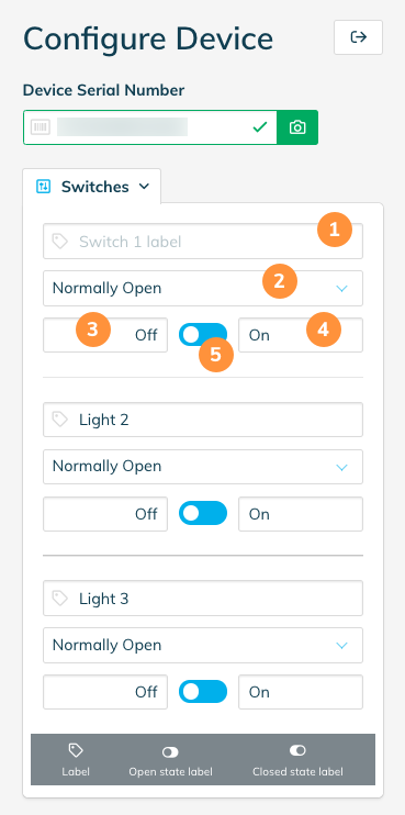
When you have logged into the Onboarding tool and entered the serial number for an device that has switching capability, a "Switches" tab will be shown.
The Switches tab won't display if the device is detected as being offline. If the Switches tab is still not visible for the device you are accessing and the device is definitely online, and the device definitely has switches, please contact Wattwatchers Support.
The number of items that appears in the Switches tab will depend on the number of available switches on the device. For example, a 6M+3SW device will have three panels shown.
Each switch has four fields that you can edit, as well as a visual indicator of the current switch state (as numbered in the screenshot above):
- The "label" provides a way for you to enter a human-friendly label of what the switch controls. For example, if the switch turns on a hot water service, you may label this "Hot Water". If it controls a light circuit for a outdoor area, you might label it "Outdoor lights".
- This drop-down allows you to set what type of contactor is installed for the switch.
- You can provide a human-friendly label for the different states that the switch can be in. The third field is a label for when the switch is in
openstate. The default value for this is "Off" to match typical installations. - Same as 3, but corresponding to the
closedstate. The default value is "On". - Located in between the switch state label fields is a switch icon depicting the current switch state. The white circle will be aligned to the switch's current state. In the image above, all switches are in the
open("Off") state. When the device is communicating properly, you can click (or tap on your mobile) this icon to change the switch state. If all is working correctly, the colour of the switch as depicted in the Onboarding tool should match the switch state lights on the device.
Changing the switch state via the Onboarding tool is not instantaneous. It may take a minute or more for the switch change to take effect.
If we detect that a device is offline, or is having communications issues, the ability to modify the switch state will be disabled.
Once you have set these fields to match the installation configuration, you can save the changes. This information will then be reported by the API, and in Wattwatchers apps (like the Dashboard), correctly. The contactor type setting is also used by the API and our applications to determine the correct message to send to the device.
Configuring using the API
You can use the /devices/{device-id} endpoint of the Wattwatchers API to modify the same settings that are available in the Onboarding tool.
When you call the GET method on this endpoint, the current state and metadata for the switches on the device is returned in the following format:
{
    "id": "{device-id}",
    "switches": [
        {
            "id": "{switch-id}",
            "state": "open"|"closed",
            "label": "{switch-label}",
            "contactorType": "NO"|"NC",
            "closedStateLabel": "On",
            "openStateLabel": "Off",
            "pending": {
                "state": "open"|"closed"
            }
        },
        ...
    ],
    ...
The number of objects in the switches collection will match the number of available switches on the device. The returned data represents the current known state of each switch on the device.
If a device experiences communication issues, the known state of the device may be out of sync with the Wattwatchers system. The device status message includes the "latestStatus" to indicate when the last status information, which includes switch state, was received from the device.
Contactors often have a physical override as part of their design. It is not possible to detect if the physical override has been enabled.
You can use the PATCH method on the /devices/{device-id} endpoint to make changes to the metadata associated with the switches for a device.
Within each switch object (i.e. each item in the switches collection):
id= the switch ID. This is the device ID followed by an underscore, and the switch number—_S1in the example below indicates this is switch one on deviceD123456789012.labelcan be a string up to 64 characters in length. Default is blank (empty string).closedStateLabelandopenStateLabelcan be a string up to 16 characters in length.- Contactor type can be
NOfor "Normally Open", orNCfor "Normally Closed".
Note that with the PATCH method, you only need to specify the changes that you want to make—i.e. you don't need to specify every attribute for every switch.
So, for example, if you just wanted to change the contactorType value for one switch, you could send a PATCH request with the payload:
{
    "id": "D123456789012",
    "switches": [
        {
            "id": "D123456789012_S1",
            "contactorType": "NO"
        }
    ]
}
Once you have set the contactorType value, you don't need to send this again, and you can simply send the state value. The API will do the required translation to trigger the correct state in the contactor.
Sending a switch state change
To change the switch state, you use the same API call as you would when you are changing the metadata associated with a switch.
For security reasons, API keys do not have switching enabled by default. If you receive a 403 Not Permitted error, please contact Wattwatchers Support to request this be enabled for your key.
As noted above, you can request a switch change for an individual switch:
{
    "id": "D123456789012",
    "switches": [
        {
            "id": "D123456789012_S1",
            "state": "open"
        }
    ]
}
Or you can request changes to multiple switches at once:
{
    "id": "D123456789012",
    "switches": [
        {
            "id": "D123456789012_S1",
            "state": "open"
        },
        {
            "id": "D123456789012_S2",
            "state": "closed"
        }
    ]
}
The API will respond with a 200 OK status or an error if there is an issue with the call.
The 200 OK response will echo the current state of the device, as if you had called the GET method immediately after.
This will list the requested state as pending if you have changed the value of the switch state from the device's current value, for example:
{
    "id": "D123456789012",
    "switches": [
        {
            "id": "D123456789012_S1",
            "state": "open"
        },
        {
            "id": "D123456789012_S2",
            "state": "open",
            "pending": {
                "state": "closed"
            },
            ...
        }
    ],
    ...
In this example, switch 1 was already in the open state, so the request to change it to open is not listed as pending. However, the second switch state did change and is marked as pending as a result.
Polling to confirm state changes
This section applies to switch state change requests only, not metadata or contactorType configuration requests.
When any device switch state change is requested via the API, this is queued to be sent to the device when it next communicates with our servers. The time it takes for a message to be received by a device will vary based on two main factors:
- The short energy reporting frequency of the device (this is 30 seconds by default)
- The number of queued messages for the device
This means it may take some time for the device to receive the switch change request. Typically this should not take longer than 1 minute.
As each request to change the state of the device is queued, your application should check to see if there is a pending state change for the switch you wish to change before issuing a state change request.
If you issue multiple requests, these will each be queued and issued in sequence, which is likely to produce undesirable results. For example, if you issue 3 PATCH requests in succession, the 3rd request may take more than 2 minutes to take effect. This may appear as though the device is unresponsive, when in fact it's just working through the queue of requests.
If you need to verify that the switch state change has taken effect, you will need to periodically poll the GET method (no more frequently than 5 seconds). Until the device has responded to confirm the switch state change, the pending value will be present.
For example, while the switch state change is pending, the GET method will return:
{
    "id": "D123456789012",
    "switches": [
        {
            "id": "D123456789012_S1",
            "state": "open",
            "pending": {
                "state": "closed"
            },
            ...
        },
        ...
    ],
    ...
When the change has been effected by the device, the GET method will return with no pending state, and the state will now reflect the new setting:
{
    "id": "D123456789012",
    "switches": [
        {
            "id": "D123456789012_S1",
            "state": "closed",
            ...
        },
        ...
    ],
    ...
Test system
Changing the switch state of a device has real-world consequences.
For your development testing, and also for integration testing, we strongly recommend that you purchase at least one additional device that can be switched with impunity—i.e. that isn't attached to anything that could be damaged by, or cause damage, when switching. We also recommend this test system include at least one of each contactor type ("Normally Open" and "Normally Closed").
For example, you may get an electrician to wire up a small test rig that includes an Auditor and 3 different incandescent lights controlled by a contactor, with each circuit monitored by the Auditor, that you can plug into a wall outlet to power up and test with.
By attaching a reasonable load (the lights) to the circuit you can verify the switch state, even if you are working remotely.
You could even use the light rig to provide visual feedback to the build state in your continuous integration system, for a bit of extra fun...